Vis-U-Etch Cupric Chloride Etcher Controller
Oxford V.U.E., Inc.
11711 Clark St., Ste 108
Arcadia, CA 91006
USA
ph.(626) 256-6557
fax(626) 256-6567
www.oxfordvue.com
Oxford V.U.E., Inc.
Vis-U-Etch 5

PO Box 661896, Arcadia, CA 91066-1896 USA
Tel. (626) 256-6557 - Fax (626) 256-6567 - www.oxfordvue.com
TABLE OF CONTENTS
ELECTRONIC SECTION - FRONT PANEL INDICATION
ELECTRONIC SECTION - INTERNAL INDICATORS
CHEMICAL BOX CONNECTOR COLOR CODE
Vis-U-Etch 5 recommended Maintenance Schedule
Analysis for Free Acid Normality
Chlorine Gas Event - Safety Procedure
CAUSES OF CHLORINE GAS RELEASE (in order of usual occurrence)
- Cupric Chloride has the highest etch factor (lowest undercut) of all common etchants known which allows for its simple fine line capability and less chance of undercutting.
Cupric Chloride has very little odor when properly balanced and is ready for use immediately even weeks after non-use.
Use extreme care in unpacking the units from their respective shipping crates. Do not pull on or kink the plastic tubing. Do not drop the white pick-up tubes -- they contain fragile float assemblies. Lift the VIS-U-ETCH units out by the cases only. The valves in the Chemical Section are wrapped individually and not connected to the plumbing fittings. Locate the valve labeled "Acid Valve" and connect it to the rear fitting from the Acid Signet and the glass tubing to the injector. Locate the valve labeled "Oxidizer Valve" and connect it to the front fitting from the Oxidizer Signet and the glass tubing to the injector. Be sure to pay attention to the "Flow" arrow on the valves. The proper direction is from the Signet to the injector. Locate the warning horn and light parts and connect them to the top of the Electronic Section. Line up the arrows on the side of each piece.
Careful thought should be given to the placement of the VUE 5 Electronic and Chemical Sections.
- Access to acid, oxidizer and spent (when used) tanks should be available.
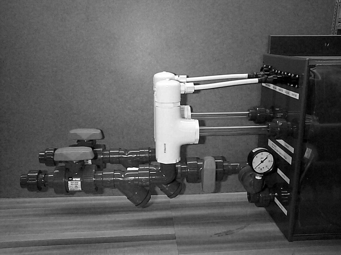 Locate Acid and Oxidizer Float/Wye Strainer/Ball Valve Assemblies (Both are interchangeable, See picture). First, connect the electrical connector to the side of the Chemical Section for Acid Low, then connect the pipe union to the corresponding Acid In fitting. Repeat for the Oxidizer Float Assembly.
Typical Chemical Section installation
The etcher should have approximately 20-25 pounds pressure to operate the Vis-U-Etch 5 as measured at the input to the Vis-U-Etch 5. If the etcher is NOT pre-plumbed for a regenerative system, proceed as follows:
- Drill and tap for a 1/2" or 3/4" N.P.T. into the etch pump manifold as close to the pump as possible. If not possible, into the top spray manifold or pipe will suffice provided enough pressure can be supplied to run the Vis-U-Etch 5 AND maintain enough pressure on the top spray nozzles.
NOTE:?If etch machine has external pump fitting, an additional bulkhead fitting need not be used. Tap this hole into output of pump manifold instead.

Optional Bubble Extractor
For the return line, perform the following:
See picture below.
- Drill a 45/64" (3/4" may be substituted) hole and tap with 1/2 inch N.P.T. in etch machine for the VUE about two-thirds the distance away from the pump intake across the etch chamber. This hole should be above the liquid level and the pipe elbowed down into the machine.
Return line / Right-Angle Etch full float (Inside etcher)
For the optional Spent system, perform the following:
- For right angle float assembly: Determine maximum liquid level desired in the etch machine and mount float level switch so that float is one (1) inch above that level. This should be in a "quiet" area of the etch machine where there are no waves from the pump and accessible for cleaning.
Remaining items:
- Connect all hoses as shown, clamping to appropriate support as necessary.
Fill etch machine with water and run to check for leaks at all connections - If there are no leaks, drain water and refill with starter etch. Be sure to prime the acid and oxidizer feed lines in manual mode until flow error lights go out when pumping and input chemistry can be seen flowing through the glass sight tubes between the valves and injector assembly. Then, clear the Input Chemical Failure Alarm circuit. See the Input Chemical Failure Alarm section in this manual for more details.
It is extremely important to setup the ventilation of the etcher properly. During normal operation of the Vis-U-Etch 5 and etcher, very little odor is produced by the etchant and therefore very little ventilation is required. If there is a strong chlorine odor while etching and/or regenerating, calibration is required (see Calibration section). The only time strong, powered ventilation is required and/or desired is when an unbalanced etchant state occurs resulting in the release of chlorine gas.
The proper amount of ventilation to have is just enough airflow to prevent any fumes in the etcher from being released into the etch room atmosphere. It is important to reduce the amount of airflow to a bare minimum due to the fact that a certain amount of water is removed from the etchant in the form of water vapor. If the etcher is left running for long periods of time while not etching any panels, the amount of water in the etchant will be reduced and the baumé will rise indicating an increase in the copper level in the etchant. Under extended periods of time, this could cause solids to form in the etchant. If the etcher is to be left on between jobs for the sake of maintaining the temperature, it is a good idea to limit the running time between jobs to no more than 10 minutes.

In a multi-chamber etcher, it is necessary to have a recirculating pump to enable proper blending of the regeneration chemistry with the cupric chloride in the etcher sump. The proper way to plumb the recirculation pump is to connect the feed to the pump from the front of the first etch chamber and the output from the pump to the rear of the final etch chamber. This ensures that the flow of etchant inside the etcher moves from last to first chamber, opposite the direction of the panels on the conveyor. On occasion, we have seen instances of the recirculation pump being plumbed the opposite direction and this can reduce the effective etch speed by as much as 10-15%. The reason is that most etching occurs in the first chamber(s) resulting in an increase in the amount of cuprous chloride in the first chamber(s), which does not etch. By having the flow of etchant moving the same direction as the panels, the cuprous chloride that forms follows the panels through the etcher, impeding the etch rate. By correctly having the flow of circulation in the etcher sump moving the opposite direction of the panels, you always have the fresh cupric chloride from the last chamber(s) moving towards the panels on the conveyor.
When connecting the Vis-U-Etch 5 to a multi-chamber etcher, it is best to sample from the first or second chamber for the Etch In and return the Etch Out approximately one-half to two-thirds the distance from the Etch In line back towards the last etch chamber (See: Items That Affect Calibration).
DO NOT connect the Vis-U-Etch 5 to the recirculation pump! The flow of etchant through the recirculation pump would have to be drastically reduced in order to provide sufficient pressure to operate the Vis-U-Etch 5.
The correct pump capacity and plumbing size is determined as follows. Select a pump and pipe size capable of moving the entire sump capacity of the etcher through the pump in five minutes or less (i.e., Fifty gallons per minute for a two-hundred-fifty gallon total sump). Too little circulation can result in wider swings in the state of the etchant. Enough circulation ensures the most homogeneous etchant solution and consistent etched results.
The VIS-U-ETCH system uses the principal of light transmission to diagnose chemical changes occurring in the etching solution. These changes are color, density, and turbidity.
When the etchant requires regeneration, the VUE uses a "trial and error" system to determine the correct chemical to add. With a choice of two chemicals to cause regeneration (acid or oxidizer) the VUE will add one, mix it with the etchant, and then look at the results as determined by the output meter. If this were the cure, it will continue to add this chemical until regeneration is complete as determined by the rising input meter. If it were not the cure, it will add the other chemical instead and examine the results. If neither helped, it will alternately add both chemicals. The VUE will never add both chemicals simultaneously in the automatic mode. The VUE system is designed to operate with the etch solution in a "starved" chemical condition (never completely regenerated). As etchant is used, starvation is increased to the point where the VUE becomes activated (as determined by the falling input meter). At this point, the etchant will have become slightly darker. Chlorine gas is generated within the solution and is immediately absorbed by the cuprous to cupric reaction. The VUE unit activates when either the cuprous chloride level becomes higher or the cupric hydroxide level becomes higher or both. Regardless of the condition, the etchant partially loses its clarity and becomes darker. Cuprous chloride is re-oxidized to cupric chloride by the introduction of oxidizer. Cupric hydroxide is dissolved by hydrochloric acid (muriatic acid), which also controls side reactions. In either case, the light cells detect a change in light transmission. The change is indicated on the meters. The oxidizer contains a buffer and catalyst which increases the etch speed and makes the etch insensitive to all but large chemical deviations. There is some lightening of the etch when the VUE adds oxidizer even if it is not needed because of sample dilution - the output meter will rise slightly whether needed or not. If oxidizer is needed, the movement of the meter will be marked. This is not the case when acid is added. If acid is added when it is not needed, the output meter will not react. If it goes negative (to the left), it indicates too much acid is in the etchant.
If etchant is not kept in a "starved" condition and the VUE is made to regenerate too early, the chlorine gas generated cannot be absorbed into the etchant and will be released into the atmosphere. The alternation of both valves back and forth indicates a need for both oxidizer and acid - this generally means the solution is in good balance. As the valves alternate, the output meter will rise momentarily and then settle back. Eventually, one mode will take over and/or regeneration will be complete.
On some machines, cavitation of the pump may cause air bubbles to be pumped with the etch solution through the VUE. These bubbles may be seen at the light cell, especially the output cell. Bubbles, due to variables, reflections, and densities, are viewed as partial opacities and will "fool" the VUE’s sensors. The optional bubble extractor will minimize this problem. In addition, the Bubble Detector will alert the operator to any additional bubbles in the etch solution whose source must be identified and corrected. In the event that the VUE lacks sensitivity or will not operate properly due to bubbles, try the following: install a plastic valve at the etch machine before the filter and bubble extractor. Use this valve to control the pressure to the VUE as directed above. Turn the valve mounted on the VUE to full "on". In extreme cases of bubbles, check the etching machine’s pump for need of repair.
The control of copper quantity in the etchant is pre-determined by the oxidizer. Many variables are associated with each etching machine (evaporation of water, venting, drag-in, drag-out, wash down of the machine, etc.). These will affect copper content in the etchant. Excessive drag-in of water from the rinse tank must be avoided as this will dilute the etchant and cause problems - etch speed will be reduced. Regeneration is exothermic, therefore heat will be developed while etching. Cooling coils are necessary. To conserve water, this slightly warmed water may be used for down stream Rinsing. Do not run excessive water through cooling coils - this is wasteful and cooling efficiency is not increased. A chiller may be desirable or necessary depending upon production levels and etcher size.
If, after etching for a while, the copper content (baumé) increases, verification of the oxidizer solution and/or etcher ventilation is in order. Daily verification of the copper content should be performed using Copper Test Procedure.
The "Acid Low" and "Oxidizer Low" lights refer to the level of chemicals in their respective tanks, not to the quantity of these chemicals in the etchant.
A sludge of an inch or less (cupric hydroxide) will form at the bottom of the etch machine with use. This is normal and must not be removed! This sludge is dissolved to some extent as the VUE adds acid - it acts as a buffer.
Note:?As a routine, when the etching machine is turned on every morning, verify that etchant has not back-flowed through the oxidizer or acid valve and into the lines coming from the tanks. A back-flow of etchant through the acid or oxidizer valve indicates a plugged etch out return line. The spent valve (when used), of course, will have etchant in it.
The Vis-U-Etch process does not use baumé (specific gravity), acid normality or ORP to determine what is needed for regeneration. We do, however, recommend keeping a baumé hydrometer in the inspection tube for a couple of reasons. The first is the baumé reading at operating temperature will pick a point and stay there (39o-45o normal range at operating temperature), unlike ORP / normality systems that fluctuate and keep diluting the etchant with water. The baumé reading is determined by oxidizer concentration, calibration setting, altitude of your location, humidity and so on. This is important in helping you to determine if anything has changed in the condition of your etchant. If that happens, you can anticipate problems and their cures rather than react to them later. The second reason is that with a baumé hydrometer floating in the tube you can easily pull it out and inspect the last drip on the bottom for clarity of the etchant. This aids in verifying the calibration of the Vis-U-Etch. For example, if the etchant is not clear green, regeneration should be taking place. If the etchant is clear green and regeneration is taking place accompanied by a chlorine smell, the calibration is set too low. Adjust both meters slightly higher (1/4 turn on each adjustment) and then check again after etching about 10-15 minutes. This gives enough time for the etchant to adapt to the new setting.
Note:?The baumé should not be allowed to rise above 45o at operating temperature. Higher readings can cause solids to form in the pipes due to a lack of sufficient moisture in the etchant. The two most common causes of this occurrence are excessive etcher ventilation (See: Etcher Ventilation), and running the etcher for long periods of time without any panels being etched. The etchant receives its water through the regeneration process. If no panels are being etched and the etcher spray pump is on, regeneration does not occur and moisture is lost. The only time the etcher should be on when not etching panels is during the warm-up period.
Two items that get discussed any time the conversation centers around etching are etch rate and etch factor. There are many things that affect both but in order to gain a better understanding of how to achieve the desired improvements you want there are a few basics to remember that you can work with.
First we’ll talk about etch rate. We frequently hear the question of how fast is our etchant. To answer this and the etch factor question, I’ll use the same simple illustration. Let’s assume that we have a single fixed nozzle etcher with a fixed tray to set our copper on.
When the copper panel is placed on the tray and the spray is turned on, the area directly under the spray nozzle starts to etch very quickly. In direct testing with this method, a one-ounce copper panel will be etched to the substrate in well under a minute under the spray. What is more important to consider, though, is that the area just _" away from the direct spray contact area, although etchant also flows across it, etches only about half as fast. The main reason for this is that the etchant directly hitting the copper changes from cupric chloride to cuprous chloride and stops etching. In order to continue etching, fresh cupric must be delivered to move aside the spent cuprous.
You can test the etch rate of your etcher under the spray nozzle by placing a copper panel on the conveyor and running it into the etch chamber. Turn on the spray pump (not oscillating) for a given number of seconds and see how long it takes to get to the substrate under the nozzle. This is also a great indicator of how much of your etch chamber is actually etching and how much etching doesn’t happen between nozzles. To illustrate my point, let’s assume we have a three foot long etch chamber with one nozzle every foot. If we compare the etch rate of that etcher with another three foot long chamber with spray nozzles every six inches, you’ll find that the conveyor moves twice as fast to etch the same amount of copper because of the increased spray contact area. During one installation of a new Vis-U-Etch 5, we modified an old etcher by almost doubling the number of spray nozzles per spray bar. Under the original spray pattern, it took the conveyor approximately 112 seconds to finish etching a one-ounce panel. After adding the additional nozzles, the conveyor sent the panel through in just 71 seconds, a decrease of more than 36% of the time needed to finish etching the panel. Many of the latest etcher designs have a marked increase in the number of nozzles per square foot or nozzle density.
The type of nozzles used is very important. Usually, full cone type nozzles etch faster than flat fan type nozzles because they deliver more volume of etchant. Fan type nozzles are becoming more popular though because of the higher etch factors needed.
In order to help remove cuprous from the panel more quickly, oscillating spray bars are often used. If the nozzle density is too low, oscillation can really improve the etch rate. If the nozzle density is as high as possible, the puddling effect of cuprous is less and the difference between oscillating and non-oscillating spray bars is less pronounced.
When oscillation is used, one of the most commonly overlooked items is the rate of oscillation. Oscillation is intended to move the cuprous puddle off the panel as quickly as possible. Depending on the size of the panel and the speed of the conveyor, you must set the oscillation rate so the "wave" of etchant moves quickly off the panel but not too quickly that it gets pushed back on. To set this rate correctly you can do this test. Increase the conveyor speed for some test panels so that some of the copper remains. Start with your oscillation rate at 20 back and forth cycles per minute. Run each panel through the etcher, one at a time, adjusting the oscillation rate by 2 cycles per minute higher between panels. What you will see is the etch rate increases and decreases like a sine wave. Pick the rate that works best for each size and thickness of your panels. Thickness changes the conveyor speed so the oscillation rate can change.
Many etchers are designed specifically to run very thin core material. To prevent cores from flipping up and getting caught inside the etch chamber, various types of top rollers are used. This can create an etch rate problem because the more interference with the spray nozzles the slower the topside etch rate becomes. The bottom is less affected because cuprous doesn’t puddle underneath it just falls off.
If spray pressure is increased, etch rate increases. More pressure means faster delivery of fresh cupric and faster removal of cuprous. This becomes very important when the spaces between the traces on your panel are very small. Now higher pressure is needed to "dig" out spent cuprous and replace it with fresh cupric. Many new etchers can operate as high as 40-50 PSI. The consideration for higher pressure will be limited by the hole sizes of your panels when these are etched. Obviously you don’t want higher pressure breaking the tents and etching the inside of the holes.
If etchant temperature is increased, etch rate increases. Higher temperatures speed up chemical reactions. The only limitation here is in the material the etcher is made of. It is generally best to run the temperature as high as the warranty of your equipment allows without exceeding it. If you are not sure about the cooling capability of your etcher set the temperature lower to be safe. Check with your etcher manufacturer to see what is the maximum recommended operating temperature.
Now it’s on to etch factor. Etch factor is essentially how straight your sidewalls are or how little under cutting is occurring. Etch factor is governed by several things.
The first is the reason you bought your Vis-U-Etch 5 to begin with. Other controllers operate using Oxidation-Reduction Potential (ORP) probes to control oxidizer and conductivity (Normality) probes to control the acid content. In order to function properly, Normality probes generally must have at least 0.5N free acid in the etchant. As you increase the free acid content, the etch factor goes down because having free acid on the panel allows the cuprous that forms to be regenerated on the surface of the copper panel. Since cupric chloride will etch copper in any direction, free acid in the spaces between traces will also etch sideways after regenerating in the space. The Vis-U-Etch 5 uses light transmission to sense changes in the clarity of the etchant. This allows us to operate at <0.04N, effectively zero free acid. At 0N, no regeneration occurs on the panel surface. The only way etching can continue is to spray more etchant from the nozzles.
That brings me to the next point. The direction the etchant hits the panel is one of the most important items in determining etch factor. Two things influence the direction. One is the type of spray nozzle. As discussed in the etch rate part of this article, there are two types of nozzles used, full cone and flat fan. While it’s true full cone nozzles generally deliver more etchant and a faster etch rate, they also spray the etchant at an angle other than 90o to the surface. Flat fan type nozzles spray much closer to 90o to the panel surface.
You can try this experiment using the one nozzle etcher I talked about in our first example. Place a thick piece of copper under the spray nozzle. Set the angle of the nozzle at 45o. Watch how the copper etches. You’ll see that the hole it creates through the panel is approximately 45o. This is because cupric chloride from the nozzle first hits the panel surface going downward, etching where it contacts. Spraying at an angle means that the path of the etchant through the metal is going sideways too.
The 45o scenario may sound a little extreme but think about how the oscillation in your etcher works. There are two types of oscillation (when used) found in most etchers.
The first is the swing type. This construction has nozzles mounted to a spray bar that turns back and forth in an arc. This points the spray at the panel within an arc that is only 90o to the panel at one spot in the arc. This angled spray lowers the etch factor.
The second type is horizontal reciprocation. This method is becoming more popular because the nozzles are mounted to spray bars that keep them pointing 90o to the panel. The whole rack of nozzles moves from side to side. Since etchant always sprays as close to 90o as possible to the panel, you get the highest etch factor or straightest sidewalls.
Most things in life are more easily understood when viewed in their simplest form. The single nozzle etcher sounds like a silly idea until you consider that it makes you focus your attention on the most important thing: how the spray contacts the panel.
No adjustment is necessary or provided.
The Input Meter has these functions:
- Amber ".2" or "Regen" LED indicates when regeneration starts and when regeneration has occurred in relation to the moving bar graph. It does NOT determine what chemical is required for regeneration.
The Output Meter has these functions:
- Red "Error" or yellow "Off-Scale" LED indicates the output of the light cell is higher or lower than the meter range. This is a normal condition at times.
Calibration of the Vis-U-Etch 5 is preset at the factory at 7 turns and should not generally be changed. Both calibration potentiometers are located in the Electronic Section on the motherboard and are labeled "In" and "Out" which corresponds with the input and output meters. Both are 10—turn potentiometers and should be set between 5 turns and 7 turns clockwise from the counter-clockwise stop. This setting will provide proper operation under most operating conditions. Should it become necessary to make a slight change to the setting, you can adjust both potentiometers in equal amounts up or down. Do not set outside of the 5~7 turn range. Too low of a setting will cause regeneration to start too early and release too much chlorine gas to be used in the cuprous to cupric reaction. A noticeable chlorine gas smell will come from the etchant and can become dangerous if operated in this manner. Too high of a setting will cause the etchant to become darker before regeneration and potentially end up with "runaway" chemical adds. This can also end up releasing unwanted chlorine gas. For these reasons we suggest not changing the settings at all but if you must, increase or decrease in _ turn increments only and wait for at least 4~5 regeneration cycles before determining if the new setting is acceptable.
It is normal for the output meter to operate in a range approximately _-_ meter lower than the input meter. This is due to the LED type construction of the light cells and their extreme sensitivity to changes in the etchant (color, clarity and pressure). If the input meter is below _ scale, the output meter will not show any bars and is considered "off-scale". This is a normal phenomenon. When the regeneration cycle begins and the proper chemical is added, a sufficient response on the output meter indicates that the light cell and meter are functioning normally.
Under certain circumstances the meters will track more closely together. This is OK also. At no point is it acceptable for the output meter to track higher than the input meter when regeneration is not occurring (i.e. input meter above the "regen" or ".2" reading).
If color of etchant is still clear emerald green when meters drop to ".2" or "Regen" starting regeneration, calibration setting is too low. Adjust "In" and "Out" calibration potentiometers together slightly higher. If left at this low setting, over regeneration will occur releasing chlorine gas.
If color of etchant turns noticeably darker and etch rate slows before meters drop to .2 or "Regen", setting is too high. Adjust "In" and "Out" calibration potentiometers together slightly lower. If left at this setting, inefficient etching speed and wider swings in the state of the etchant will occur.
If meters are slightly readjusted, etch boards and allow VUE 5 to regenerate several cycles. Recheck to see if the color/clarity of the etchant is clear emerald green with no chlorine smell when the Input Meter reaches the "Cal" point at about _ scale.
NOTE: Proper calibration should be verified every month whether adjustment is needed or not. Large variations in calibration accuracy can cause over regeneration and the release of chlorine gas.
Understanding "what" you are calibrating is the secret to good control of your etchant and chemical efficiency. The calibration potentiometers are adjusting the operating range of the meters. The higher (more clockwise) the setting, the higher the meters read. More counter-clockwise means a lower meter reading. A higher setting starts regeneration later while a lower setting starts regeneration sooner. The objective is to set the input meter to the proper regeneration start/stop setting and then match the number of turns on the output meter.
We know that under all different "normal" operating conditions, the calibration potentiometers will be set somewhere in the range of 5-7 turns clockwise from the counter-clockwise stop. Use the following illustration and tables to improve your understanding of the calibration process.
 As you can see, the illustration shows three possible return line locations from the VUE 5.
If "A" is used, the Etch In and Etch Out are too close together and a lower calibration setting would be required. This is due to the fact that the regeneration chemistry from the etch out line reaches the etch in line too quickly without regenerating the rest of the etchant in the tank. Therefore, regeneration would have to start sooner to allow more chemistry to enter the etchant tank. This would NOT be a good setup.
If "B" is used, the Etch In and Etch Out are the correct distance apart (approximately two-thirds the distance across the tank) and proper calibration is easy. This setup allows enough distance between Etch In and Etch Out to facilitate proper regeneration while maintaining a buffer zone to the right of the Etch Out to protect against over-regeneration.
If "C" is used, by the time the regeneration chemistry works its way from the Etch Out back to the Etch In, it is likely that too much chemistry may be added and a chlorine smell would be evident. In this scenario, the calibration setting would have to be very high to prevent over-regeneration. This setup is also NOT recommended.
The purpose of the illustration is to show the relationship of distance between Etch In and Etch Out and the calibration setting. Closer together means a lower setting. Further apart means a higher setting.
The correct ratio of acid/oxidizer usage at our standard oxidizer concentration is 1.6:1. Put another way, 8 gallons of acid should be used for every 5 gallons of oxidizer. This can be monitored by observing at least six regeneration cycles. Refer to the table below.
| Acid | Oxidizer | Calibration Is: |
| 1 | 2 | Too low, turn calibration knobs clockwise |
| 1 | 1 | Too low, turn calibration knobs clockwise |
| 1.6 | 1 | Correct |
| 2 | 1 | Too high, turn calibration knobs counter-clockwise |
Calibration By Acid/Oxidizer Usage 1
The numbers refer to the amount (ratio) of acid and oxidizer used. If usage is one part acid to two parts oxidizer, the calibration setting is too low. Increase the setting and wait about six more regeneration cycles to begin checking your usage again. The waiting time is needed to allow the chemistry to adapt to the new setting. Do NOT turn the knobs more that _ turn in either direction at a time before checking the results. Always make sure the knobs are set to the same number of turns.
If bulk tanks are used, it becomes more difficult to determine the amount of chemistry used. An alternative method is to add the total length of time that acid and oxidizer are pumped during the six-regeneration cycle test. Acid is added more slowly through the VUE 5 than is oxidizer because of the reaction/meter reading requirement. The approximate flow rates for each capacity VUE 5 are as follows:
| VUE 5 Capacity | Etchant Flow Rate (gpm) | Acid Flow Rate (gpm) | Oxidizer Flow Rate (gpm) |
| #9 | 2.5 | 0.8 | 1.4 |
| #11 | 5.0 | 2.2 | 3.4 |
| #14 | 9.0 | 3.5 | 4.5 |
Capacity Vs. Acid/Oxidizer Flow Rate 1
For example, on a #9 VUE 5, if acid was added for 10 minutes and oxidizer was added for 4 minutes, the amount used would be 8 gallons of acid and 5.6 gallons of oxidizer. You can use this table to determine the approximate amount of acid and oxidizer used. Although this does not measure an exact amount of chemical used, it is close enough to use for approximate calibration settings.
The purpose of this circuit is to prevent the addition of either acid or oxidizer for more than 2_ minutes without needing to be reset.
In automatic mode, if either chemical is continuously added for more than 2_ minutes, the check calibration LED on the motherboard and chemical (Acid or Oxidizer) flow error light will come on. The output meter will drop and the Vis-U-Etch 5 will switch to the other chemical after 7 seconds. This will reset the check calibration circuit. If the other chemical does not cause a sufficient reaction in the output meter, the Vis-U-Etch 5 will once again switch back to the original chemical. This is to check and see if chemical dilution is occurring. If the other chemical does react strongly like the first, most likely the calibration setting is too low or too high and should be adjusted (See Calibration). This would be evident by the check calibration LED lighting every 2_ minutes.
Even if the calibration setting is correct, there will be times when the etchant requires more than 2_ minutes of one chemical. By qualifying this add with 7 seconds of the other (non-reactive) chemical, you are proving the calibration setting to be correct and adding 7 seconds of the wrong chemical will not have any significant impact on the etchant.
In manual mode, the safety of this circuit is even more pronounced. When either acid or oxidizer is added manually, there is no automatic switching between chemicals so the check calibration circuit does not reset automatically either. In order to rest the circuit, both chemical switches must be turned off. Once off, the circuit resets and automatic or manual chemical adds can be resumed. The main purpose of this feature for manual operation is to prevent an etch operator from inadvertently setting the switch to manual operation and then walking away creating a runaway chemical add.
On the motherboard, there is a jumper setting for the check calibration circuit that says "Etcher Size", "Large" or "Small". This is actually the length of the time-out cycle.
For the small (factory) setting, the time-out is the 2_ minute setting mentioned so far. In the case of some installations, the capacity of the selected size of Vis-U-Etch 5 may be only 10% ~ 20% larger than the amount of copper that can be added to the sump continuously. In such cases, it may be frequently required for the Vis-U-Etch 5 to add one chemical for longer than 2_ minutes. This would cause the 2_-minute limitation to be a problem. For that reason, we added the "Large" jumper setting. This increases the time-out to 4_ minutes.
As a precaution, we strongly recommend that you contact the factory before changing to this setting. There may be other issues at work such as etcher circulation (discussed previously) that may indicate a false reason for increasing the time-out setting.
The Bubble Detector circuit is preset at the factory and generally does not require re-calibration. Furthermore, once calibration is properly set no additional adjustments should be needed.
- Turn the etcher on. After approximately 65 seconds, the VUE 5 will turn on.
Note:?For both adjustments, make sure that you do not go any further than the point at which the sound or LED just changes. Also, remember that the Bubble Detector operates in a very sensitive range. If etchant is allowed to get noticeably out of balance (dark or cloudy), the Bubble Detector will no longer sound off. Remember, the Bubble Detector lets you know when a problem starts. If the problem is not identified and corrected when first discovered and if the etchant is allowed to get out of balance, you are defeating the purpose of the Bubble Detector's early warning.
The Timed Sequence Circuit is a unique switching circuit that switches modes from acid to oxidizer and back. Since the addition of acid to the etchant is not as apparent in its reaction the circuit will always start in the acid mode first. If acid is not the curing element, as determined by the Output Meter, it will then automatically switch to the oxidizer mode.
Experimentation has shown that greater economy of chemicals is realized by acid first trial and this automatic injection of acid first will occur whenever regeneration is initiated.
Settings for the Timed Sequence Circuit are preset at the factory and can not be changed. If you suspect a problem with the timing cycle, call for technical assistance.
110V-120V AC 60HZ 2.5A. Standard USA Grounded Outlet.
DO NOT use on same circuit as electric motors or with other devices that cause electrical interference.
I. Oxidizer:?Various. Contact Oxford V.U.E., Inc. for an approved vendor.
II. Acid:?Use only water white acid (31%, 20o Baumé, Fe <1ppm, Sulfates <250ppm).
SODIUM CHLORATE BASED OXIDIZER (NaClO3) is a powerful oxidizing agent. A fire hazard exists when it is mixed and dried with any oxidizable material such as wood, paper, etc. Instruct ALL personnel handling this chemical of its properties - read the Material Safety Data Sheet supplied with ALL chemicals. There is no longer a fire hazard once the oxidizer mixes with the etchant as controlled by the VUE.
MURIATIC (hydrochloric) ACID is a strong acid. Never mix acid and chlorate, as a violent chemical reaction occurs and an abundance of chlorine gas will be liberated.
As a rule, etchant has very little odor to it; however, powered venting is required. A strong chlorine odor indicates an out of balance chemistry (see: Causes of Chlorine Gassing). If chlorine is detected, turn the VUE flow valve "off". Etch boards until the excess chlorine is consumed and then check for the cause.
DO NOT TURN THE ETCH MACHINE "OFF" WHILE REGENERATION IS IN PROCESS. Allow at least five (5) minutes after all lights go off (except pilot and spent lights) before turning off etch to flush the lines of any concentrated chemicals.
|
Oxidizer Error:
|
Indicates low quantity of oxidizer in barrel or Oxidizer Flow Error when Input Chemical Failure Alarm circuit is activated. Look at the Input Chemical Failure Alarm board to determine which item failed. (See Input Chemical Failure Alarm Circuit)
|
|
Spent Full:
|
Alerts operator to stop regeneration of etchant until Spent Tank is emptied.
|
|
Acid Error:
|
Indicates low quantity of Muriatic (hydrochloric) Acid in acid barrel or Acid Flow Error when Input Chemical Failure Alarm circuit is activated. Look at the Input Chemical Failure Alarm board to determine which item failed. (See Input Chemical Failure Alarm Circuit)
|
|
Meters:
|
Red "Error" or yellow "Off-Scale" LED indicates light cell output above or below the meter range. Both meters are inter-changeable. Electronic Meter off-scale is accompanied by horn sound when selected. DIP switch 4 of SW1 on Motherboard, when "ON", is for Input Meter off-scale. DIP switch 3 of SW1 on Motherboard, when "ON", is for Output Meter off-scale. The ".2" or "Regen" LED is on whenever the meter is reading below approximately _ scale. The ".4" or "Hold" LED is on whenever the meter is above approximately _ scale. The "Cal." LED is on whenever the meter is approximately mid-scale.
|
|
Oxidizer Pumping:
|
Indicates when Oxidizer Valve in Chemical Section is open allowing Oxidizer to be added to the etchant.
|
|
Spent Pumping:
|
Indicates when Spent Valve in Chemical Section is open allowing excess etchant to be pumped into the Spent Tank.
|
|
Acid Pumping:
|
Indicates when Acid Valve in Chemical Section is open allowing Acid to be added to the etchant.
|
| Board | L.E.D. | Color | Description |
| Motherboard | L1 | Green | Oxidizer Pumping |
| L2 | Green | Acid Pumping | |
| L3 | Green | Spent Pumping | |
| L4/AS | Green | Auto Spent Timer Active | |
| L5 | Amber | Motherboard Power On (After Time Delay When Etcher Is Turned On) | |
| L6/Chck Calibration | Red | See "Check Calibration Circuit" | |
| L7/AO | Amber | Auto Oxidizer (During Regeneration: On=Oxidizer, Off=Acid) | |
| L8/AV | Amber | Auto Valve Command. On During Regeneration. | |
| L9/TA | Amber | Indicates timer circuit is active. Flashing during regeneration if insufficient output meter reading from current chemical add. | |
| Power Supply Board | "Line" | Green | Indicates when VUE 5 is plugged in to a live wall outlet and the input ( 3A ) fuse is good. |
| "12AC" | Green | Indicates internal 12 volt A/C power and that 12 Volt ( 3A ) fuse is good ( On whenever unit is plugged in ). | |
| "6AC" | Green | Indicates internal 6 volt A/C power and that 6 Volt ( 2A ) fuse is good (On whenever unit is plugged in ). | |
| "GFI" | Red | LED lights when Ground Fault Circuit Interrupter is "tripped". Goes off when GFI is reset. (NOTE: Repair electrical problem BEFORE resetting GFI to prevent electrical shock and further tripping of GFI) | |
| "117AC" | Green | Indicates internal 117 volt A/C power and that 117 Volt (2A) fuse is good (On whenever unit is plugged in ). | |
| Bubble Detector Board: | "Power" | Green | Indicates power for Bubble Detector Board |
| "Calibrate" | Amber | See "Bubble Detector Calibration" section | |
| "Bubbles" | Red | Indicates when bubbles are sensed by Bubble Detector Light Cell. Also accompanied by "chortling" horn sound. |
| Flow Detector Board | L1 Acid Valve Open | Amber | Acid Valve Open |
| L2 Acid Flow | Green | Acid Flow | |
| L3 Acid No Flow | Green | Acid No Flow | |
| L4 Acid Flow Error | Red | Indicates Acid Flow Error when flow is incorrect (No flow when required / Flow when not required). Accompanied by horn sound on Acid Flow Error when DIP switch 6 of SW1 on Motherboard is "ON". | |
| L5 Oxidizer Valve Open | Amber | Oxidizer Valve Open | |
| L6 Oxidizer Flow | Green | Oxidizer Flow | |
| L7 Oxidizer No Flow | Green | Oxidizer No Flow | |
| L8 Oxidizer Flow Error | Red | Indicates Oxidizer Flow Error when flow is incorrect (No flow when required / Flow when not required). Accompanied by horn sound on Oxidizer Flow Error when DIP switch 5 of SW1 on Motherboard is "ON". | |
| Input Chemical Failure Alarm Board | Power | Green | Indicates power for Input Chemical Failure Alarm Board |
| Oxi Empty | Red | Indicates automatic shutdown due to empty oxidizer barrel | |
| Acid Empty | Red | Indicates automatic shutdown due to empty acid barrel | |
| Oxi Flow | Red | Indicates automatic shutdown due to oxidizer flow error for longer than five seconds | |
| Acid Flow | Red | Indicates automatic shutdown due to acid flow error for longer than five seconds |
|
Oxidizer Low:
|
Indicates low quantity of oxidizer in barrel or Oxidizer Flow Error when Input Chemical Failure Alarm circuit is activated. Look at the Input Chemical Failure Alarm board to determine which item failed. (See Input Chemical Failure Alarm Circuit)
|
|
Spent Full:
|
Alerts operator to stop regeneration of etchant until Spent Tank is emptied.
|
|
Acid Low:
|
Indicates low quantity of Muriatic (hydrochloric) Acid in acid barrel or Acid Flow Error when Input Chemical Failure Alarm circuit is activated. Look at the Input Chemical Failure Alarm board to determine which item failed. (See Input Chemical Failure Alarm Circuit)
|
|
Oxidizer Flow Error:
|
Indicates improper flow of oxidizer (No flow when required / Flow when not required). Active any time VUE 5 is on when error is detected.
|
|
Bubble Detector:
|
Indicates when bubbles are passing through Bubble Cell.
|
|
Acid Flow Error:
|
Indicates improper flow of acid (No flow when required/Flow when not required). Active any time VUE 5 is on when error is detected.
|
|
Input Monitor:
|
Indicates when Input Monitor is off-scale.
|
|
Pilot:
|
Indicates power to Remote Box
|
|
Output Monitor:
|
Indicates when Output Monitor is off-scale.
|
|
GFI:
|
Indicates when Ground Fault Circuit Interrupter has "tripped" due to an electrical malfunction. Stays on until reset button on Power Supply Board GFI is depressed. (NOTE: Repair electrical malfunction BEFORE GFI is reset to prevent electrical shock and further tripping of GFI)
|
|
Check Calibration:
|
Indicates Check Calibration Circuit has timed-out. (See Check Calibration Circuit)
|
|
Oxidizer Pumping:
|
Indicates when Oxidizer Valve in Chemical Section is open allowing Oxidizer to be added to the etchant.
|
|
Spent Pumping:
|
Indicates when Spent Valve in Chemical Section is open allowing excess etchant to be pumped into the Spent Tank.
|
|
Acid Pumping:
|
Indicates when Acid Valve in Chemical Section is open allowing Acid to be added to the etchant.
|
|
Category
|
Item
|
Color Order From Connector End
|
|
Valves
|
||
|
Acid
|
Green/Red
|
|
|
Oxidizer
|
Green/Blue
|
|
|
Spent
|
Green/Yellow
|
|
|
Light Cells
|
||
|
Input
|
Blue
|
|
|
Output
|
Green
|
|
|
Bubble
|
Red
|
|
|
Signets
|
||
|
Acid
|
Yellow/Red
|
|
|
Oxidizer
|
Yellow/Green
|
|
|
Pressure Switch
|
Yellow
|
Color code refers to the color of the tie wraps around each wire starting from the connector side of the Chemical Section Internal Wiring Harness.
This circuit with the accompanying red flashing light and horn is designed to shut down the automatic introduction of acid and oxidizer in the event of empty acid/oxidizer feed tanks or acid/oxidizer flow error for more than five seconds duration. By shutting down automatic input chemical additions, the etchant will turn black if the error is not repaired and no chlorine gas will be released. When repairs are made and the Input Chemical Failure Alarm is reset, the Vis-U-Etch 5 will regenerate the etchant back to its normal clear green state without a chlorine gas release.
When either the acid or oxidizer feed tank becomes empty as indicated by the barrel low/error lights on the Remote Box and Electronic Section, the Input Chemical Failure Alarm will shut down the automatic acid and oxidizer input. The warning light will flash and the horn will sound. This will prevent the over-addition of the opposite chemical, resulting in chemical imbalance and possible release of chlorine gas. To correct this situation, the empty feed tank must first be refilled. Then the switch for that chemical on the Electronic Section must be operated in manual until the barrel low/error lamps go off and the corresponding flow error lamp goes off. Return the switch from manual to automatic mode and push the reset on the Input Chemical Failure Alarm board to restore normal operation and clear the alarm.
If this warning occurs and the feed tank is NOT empty, check for a leak from the feed tank to the valve inside the VUE 5. Since the chemical additions are made using the vacuum generated by the injector and controlled by the valves, any leaks in the feed pipes will cause the acid or oxidizer to return to the barrel and turn on the Input Chemical Failure Alarm.
Note:?All feed pipes should be sealed by PVC cement or 100% Silicone sealer. DO NOT USE TEFLON® TAPE! IT DOES NOT WORK! IT WILL START LEAKING!
As to the Acid/Oxidizer Flow Error warnings, it is normal for the flow error lamps to come on and then go off after each chemical is pumped. This is to verify proper warning system operation and should be observed periodically while etching. What is actually happening is the Signet flow detectors are used to monitor two types of errors. They are no flow when the valve is supposed to be open and flow when the valve is supposed to be closed. Thus, when each valve closes, it takes a couple of seconds for the flow detector’s paddle wheel to stop spinning, displaying a flow when valve closed error.
What the Input Chemical Failure Alarm circuit does is to monitor this circuit for a flow error exceeding approximately five seconds. Under normal circumstances, a flow error does not occur for more than two or three seconds and this would not trip the Input Chemical Failure Alarm circuit. This is also less than the seven second switching time between chemicals when they alternate. In the event this error occurs, the corresponding Oxi Flow or Acid Flow error led on the Input Chemical Failure Alarm board will light, automatic acid/oxidizer input will stop, the warning light will flash and the horn will sound.
To clear the error, you must first determine the cause of the flow error. First, operate the valve manually and observe the glass tube between the valve and the injector. If there is no flow, check for valve failure, a broken or leaking feed pipe or an obstruction in the feed pipe. If there is sufficient flow, check for debris in the flow detector preventing proper operation and clean out the lines to keep it from happening again. If the flow error is caused by acid/oxidizer flow when the valve is supposed to be off, check for a stuck open valve or debris in the valve preventing it from closing. Replace the valve or clean the feed pipe as necessary.
After the problem has been fixed, push the reset button on the Input Chemical Failure Alarm board to resume normal operation. Watch the Vis-U-Etch 5 for a sufficient amount of time to be sure the problem has really been corrected.
Remember:?Any time a leak is repaired or empty acid or oxidizer barrels are refilled, you must operate the acid/oxidizer valve in manual mode long enough to clear the empty barrel and flow error warnings before returning to automatic operation and resetting the Input Chemical Failure Alarm circuit. You can watch the input acid/oxidizer through the glass tubes at the injector for verification of chemical flow.
I.?Bubble Extractor (when used) - when pressure to the VUE drops, inspect/change filter cartridge in Bubble Extractor mounted on the etch machine. Remove filter bowl by hand, clean bowl, reinstall filter media and bowl, using dielectric compound on O-ring. Hand-tighten only. NOTE: A filter is not necessary for use with the Bubble Extractor.
- Check Oxidizer and Acid Wye Strainers every time the respective tank is empty for obstructions or debris.
III.?Keep the cabinet clean with 210 Plastic Cleaner or equivalent. Use no solvents on the case.
IV.?When replacing any plumbing parts, use silicone dielectric compound only on the O-rings. For threaded pressure switch or other permanent fittings, use 100% silicone sealer. NEVER USE TEFLON TAPE ON FITTINGS. Teflon tape WILL leak and cause operating problems.
Daily:
Pressure at Vis-U-Etch 5 (If down, check Wye Strainer and Blue Filter/Bubble Extractor).
Operate each valve manually, check for fluid movement at glass tubes.
Inspect for leaks: Repair immediately.
Copper content of etchant (See: Copper Analysis).
Baumé of etchant (See: The Baumé Inspection Tube).
Monthly:
Verify calibration setting. (Should not be changed)
Annually:
Replace solenoid valves.
Replace ball valves.
Replace black Parker fittings.
Replace all o-rings.
Two (2) valves are used for vacuum operation. The spent valve (when used) is the only pressure-operated valve. If any leakage is observed from a valve, replace it. These valves have a custom Teflon® core, available from Oxford V.U.E., Inc., for use with etchant chemicals. Standard valve replacements are not designed for this purpose and will fail quickly.
The chemistry of the VUE system lends itself well to pollution control and great savings of water. For an average etch machine, a 50-gallon open tank placed under the rinse tank with a small recirculating chemical pump will suffice. Fill the tank with water and add approximately one (1) liter of muriatic acid. Drop in pieces of scrap aluminum (not necessarily pure aluminum). As the boards come out of the etch machine, the rinse water will remove the copper and drain into the tank. A reaction occurs that will precipitate copper out as copper metal and the aluminum will go into solution. At the end of the shift, or better, the following day, the liquid may be drained out of the tank and the trapped copper metal removed. This liquid will contain aluminum chloride, which is currently not considered a pollutant. The acid will be consumed. The pump should have a filter before it in order to prevent particles from clogging either the pump itself or the jets.
- Pipette a 1.0 ml. sample of cupric chloride etching solution into a 250 ml. Erlenmeyer flask. For best accuracy, a "To Contain" (TC) pipette is recommended. After dispensing cupric solution from pipette wipe down the exterior of the pipette and rinse out the interior with DI water into the sample flask-total DI water addition should be approximately 50 ml.
Calculations:
Copper by ounces per gallon =?ml. sodium thiosulfate x 6.354
?7.5
- Pipette a 1.0 ml. sample of cupric chloride etching solution into a 250 ml. Erlenmeyer flask. For best accuracy, a "To Contain" (TC) pipette is recommended. After dispensing cupric solution from pipette wipe down the exterior of the pipette and rinse out the interior with DI water into the sample flask-total DI water addition should be approximately 50 ml.
In order to regenerate or convert cuprous chloride (CuCl) back to cupric chloride (CuCl2), chlorine gas (Cl2) must be added to the etchant. The safest method of chlorine gas addition is to combine two agents in the etchant that produce chlorine gas that is immediately consumed by the cuprous to cupric reaction. This is how your Vis-U-Etch 5 operates. Combined with a sodium (Na) buffer/catalyst, the Vis-U-Etch 5 is the safest and most stable of all systems. There is, however, the ever-present possibility of a chlorine gas event due to improper calibration, mechanical failure or operator error. At the first sign of a chlorine gas smell, calibration and/or mechanical failure should be checked. If corrected immediately, the etchant will remain balanced and no loss of production will occur. If left unchecked, a significant chlorine gas release can occur, stopping production and clearing the etch room of all personnel. In a perfect world, all personnel would read all owner's/procedure manuals and be properly trained in the operation and safety of the equipment they use. Realizing that sometimes things don't go as planned, here is the proper way to handle a chlorine gas event:
- Turn off the etcher and all equipment except for room/etcher ventilation.
In the event of failure of the VIS-U-ETCH, regeneration may be accomplished manually while repairs are being made.
Obtain two (2) small plastic bottles with squire tops (dish washing soap bottles work fine). Label one "acid" and the other "oxidizer" and fill these bottles with their respective chemicals. When regeneration of the etch is necessary as determined by its darker color (loss of clarity), do the following:
- Take a small sample in a beaker.
?CAUTION: Do not add too much acid as chlorine gas may be liberated.
It is advisable to keep the first barrel(s) of spent etch that is generated so that in the event of catastrophic loss of etchant (incorrectly mixed chemicals, dilution of etch, etc.), the etching machine may be dumped and restarted.
CAUSES OF CHLORINE GAS RELEASE (in order of usual occurrence)
|
|
|
| Low copper content. | Get copper up to normal (see text) |
| Improper calibration. | Recalibrate. (Get copper up to normal first) |
| Too much acid. | Turn off VUE flow valve. Find reason for excessive acid. (leaky valve, etc.) |
| Yellow acid or chlorate. | Use water white acid. Yellow "fools" the light cells. |
|
|
|
|
| Salt crystals form overnight. May clog lines or VUE injector. | Copper level too high. | Add water to etch machine. |
| Low reading on meters, may display "Off-Scale". | Copper content to high. | Add water or salt water to etch. |
| Filters in oxidizer or acid pickup tubes clogged. | Clean filters. | |
| Injector plugged with salt or foreign material. | Back flush lines with water to clear. | |
| Etching too fast for VUE to keep up. | Allow more space between panels being etched on conveyor. | |
| VUE unable to regenerate fast enough to keep up with etching all or most times. | VUE 5 capacity too low. | Contact Oxford V.U.E., Inc. for Chemical Section upgrade. |
| Meters too sensitive, may display "Off-Scale". | Copper content too low. | Check for water diluting the etchant. Use Copper Test Procedure to determine copper level. |
| Etch temperature too low. | Raise etchant temp. to 125°F (52°C). |
|
|
|
|
| System does not come on or goes on and off while regenerating and releasing spent etchant. | Filter in Etch In line dirty. | Clean Filters. |
| Flow valve improperly set. | Readjust flow valve to 20 - 25 PSI. | |
| Etching machine pressure low. | Check etching machine pressure at VUE. 20 - 25 lbs required. | |
| Etching speed slow. | Temperature low. Copper content low. | Adjust to normal. Check copper content. |
| Rinse water diluting etch. | Minimize any water drag-in to etch. | |
| Regeneration slow. | Filters in oxidizer and/or acid barrel pickup tubes clogged. | Clean filters. |
| Etch machine pressure low, causing slow injection. | Clean filters. | |
| Rapid movements, fluctuations of meters, or insensitivity. | Air bubbles in etch. | See Bubble Detector Circuit. |
| Etch moving backwards, e.g., from etch machine to barrels. | Blockage in return line from VUE. | Clear restriction or blockage. Make sure there are no valves in return line. |
| Leaky valve. | Replace valve. | |
| Low etchant pressure. | Bring pressure to 20-25 pounds. | |
| Chlorine gas. | Turn off VUE flow valve. Etch boards until gas is eliminated. See text "Chlorine Gas Event-Safety Procedure". | |
| Spent Valve won’t turn off (spent pumping light is off). | Defective valve or valve core. | Replace valve or valve core. |
| Pressure too high | Reduce Etch In pressure to 20-25 PSI | |
| Movement in output meter only. Flow Error and/or Bubble Error indicated. | Air leak in pickup tubes or fittings on vacuum lines. | Look for bubbles in lines and repair. |
|
|
|
|
| Acid Flow Error light on, Acid Pumping light on. (Bubble Detector may be on also.) | Little or no Acid coming through tubing, bubbles noted in tubing. | Locate leak between Acid barrel and Chemical Section. Repair leak. See Input Chemical Failure Alarm Circuit section. |
| Oxidizer Flow Error light on, Oxidizer Pumping light on. (Bubble Detector may be on also.) | Little or no Oxidizer coming through tubing, bubbles noted in tubing. | Locate leak between Oxidizer barrel and Chemical Section. Repair leak. See Input Chemical Failure Alarm Circuit section. |
| Acid Flow Error light on, Acid Pumping light off. | Acid coming through tubing due to stuck open Acid Valve. | Repair or replace Acid Valve. See Input Chemical Failure Alarm Circuit section. |
| Oxidizer Flow Error light on, Oxidizer Pumping light off. | Oxidizer coming through tubing due to stuck open Oxidizer Valve. | Repair or replace Oxidizer Valve. See Input Chemical Failure Alarm Circuit section. |
| Bubble Detector light on. | Small leak in Acid or Oxidizer input tubing. | Repair leak. |
Oxford V.U.E., Inc. herein referred to as the Company, warrants VIS-U-ETCH to be free from defects in material and workmanship under the prescribed installation and under normal use and service.
The Company’s obligation under this warranty is limited to repairing or replacing, at its option, any part or parts thereof, claimed to be defective, which shall, within six (6) months after delivery to the original purchaser, be returned prepaid to the Company. The six months warranty period shall extend to all parts.
Parts which have been modified, disassembled or abused will void the warranty on such parts.
Parts returned to the Company shall be accompanied by a statement describing the problem, the date placed in service and examination of the part shall disclose the company’s satisfaction to have been defective.
This warranty is in lieu of any other warranties, expressed or implied.